Basic Info.
Product Description
Description
1. Scope of application
This Installation Manual is suit for the Fiber Optic Splice Closure (Hereafter abbreviated as FOSC), as the guidance of proper installation.
The scope of application is: aerial, underground, wall-mounting, duct-mounting, handhole-mounting. The ambient temperature ranges from -40ºC to +65ºC.
2. Basic structure and configuration
2.1 Dimension and capacity
Outside dimension (LxWxH) | 460×182×120 (mm) |
Weight (excluding outside box) | 2300g-2500g |
Number of inlet/outlet ports | 2 (pieces) on each side (total 4 pieces) |
Diameter of fiber cable | Φ5-Φ20 (mm) |
Capacity of FOSC | Bunchy: 12-96(Cores) Ribbon: max. 144(Cores) |
2.2 Main components
No. | Name of components | Quantity | Usage | Remarks | |
1 | Housing | 1 set | Protecting fiber cable splices in whole | Internal diameter: 460×182×60 (mm) | |
2 | Fiber optic splice tray (FOST) | max. 4 pcs (bunchy) max.4 pcs (ribbon) | Fixing heat shrinkable protective sleeve and holding fibers | Suitable for: Bunchy:12,24(cores) Ribbon:6 (pieces) | |
3 | Foundation | 1 set | Fixing reinforced core of fiber- cable and FOST |
| |
4 | Seal fitting | 1 set | Sealing between FOSC cover and FOSC bottom |
| |
5 | Port plug | 4 pieces | Sealing empty ports |
| |
6 | Earthing deriving device | 1 set | Deriving metallic components of fiber cable in FOSC for earthing connection | Configuration as per requirement | |
2.3 Main accessories and special tools
No. | Name of accessories | Quantity | Usage | Remarks |
1 | Heat shrinkable protective sleeve |
| Protecting fiber splices | Configuration as per capacity |
2 | Nylon tie |
| Fixing fiber with protective coat | Configuration as per capacity |
3 | Insulation tape | 1 roll | Enlarging diameter of fiber cable for easy fixing |
|
4 | Seal tape | 1 roll | Enlarging diameter of fiber cable which fits in with seal fitting | Configuration as per specification |
5 | Hanging hook | 1 set | For aerial use |
|
6 | Earthing wire | 1 piece | Putting through between earthing devices | Configuration as per requirement |
7 | Abrasive cloth | 1 piece | Scratching fiber cable |
|
8 | Labeling paper | 1 piece | Labeling fiber |
|
9 | Special wrench | 2 pieces | Fixing bolts, tightening nut of reinforced core |
|
10 | Buffer tube | 1 piece | Hitched to fibers and fixed with FOST, managing buffer | Configuration as per requirement |
11 | Desiccant | 1 bag | Put into FOSC before sealing for desiccating air. | Configuration as per requirement |
3. Necessary tools for installation
3.1 Supplementary materials (to be provided by operator)
Name of materials | Usage |
Scotch tape | Labeling, temporarily fixing |
Ethyl alcohol | Cleaning |
Gauze | Cleaning |
3.2 Special tools (to be provided by operator)
Name of tools | Usage |
Fiber cutter | Cutting off fibers |
Fiber stripper | Strip off protective coat of fiber cable |
Combo tools | Assembling FOSC |
3.3 Universal tools (to be provided by operator)
Name of tools | Usage and specification |
Band tape | Measuring fiber cable |
Pipe cutter | Cutting fiber cable |
Electrical cutter | Take off protective coat of fiber cable |
Combination pliers | Cutting off reinforced core |
Screwdriver | Crossing/Paralleling screwdriver |
Scissor |
|
Waterproof cover | Waterproof, dustproof |
Metal wrench | Tightening nut of reinforced core |
3.4 Splicing and testing instruments (to be provided by operator)
Name of instruments | Usage and specification |
Fusion Splicing Machine | Fiber splicing |
OTDR | Splicing testing |
Provisional splicing tools | Provisional testing |
Notice: The above-mentioned tools and testing instruments should be provided by the operators themselves.
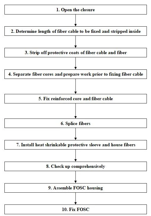
4. Installation flow chart


More products
Company information
Package & Shipping
Customer feedback
FAQ
